PURPOSE OF COMPRESSOR
The compressor section of the gas
turbine engine has many functions. Its primary function is to supply air in
sufficient quantity to satisfy the requirements of the combustion burners.
Specifically, to fulfill its purpose, the compressor must increase the pressure
of the mass of air received from the air inlet duct, and then, discharge it to
the burners in the quantity and at the pressures required.
A secondary function
of the compressor is to supply bleed-air for various purposes in the engine and
aircraft. The bleed-air is taken from any of the various pressure stages of the
compressor.
The exact location of the
bleed ports is dependent on the pressure or temperature required for a
particular job. The ports are small openings in the compressor case adjacent to
the particular stage from which the air is to be bled
Air is often bled from the final or highest
pressure stage since, at this point, pressure and air temperature are at a
maximum.
Some of the current applications of bleed air
are:
1.
Cabin
pressurization, heating, and cooling;
2.
Deicing
and anti-icing equipment;
3.
Pneumatic
starting of engines; and
4.
Auxiliary
drive units (ADU).
The two principal
types of compressors currently being used in gas turbine aircraft engines are
1.
CENTRIFUGAL FLOW
COMPRESSOR
2.
AXIAL FLOW COMPRESSOR
CENTRIFUGAL COMPRESSOR
CONSTRUCTIONAL FEATURES
The centrifugal-flow compressor consists
of an impeller, a diffuser, and a compressor manifold. Generally centrifugal compressors are limited
to two stages due to efficiency concerns.
The two main functional elements are the
impeller and the diffuser. Although the diffuser is a separate unit and is
placed inside and bolted to the manifold, the entire assembly (diffuser and
manifold) is often referred to as the diffuser. The impeller is usually made
from forged aluminum alloy, heat treated, machined, and smoothed for minimum
flow restriction and turbulence.
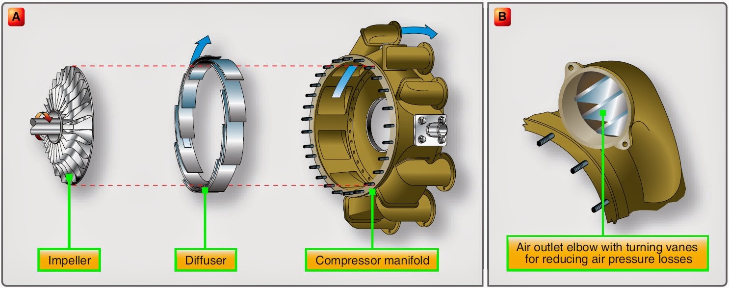

The above two figures shows
the basic construction of a centrifugal compressor
Principle of Operation
Air is sucked into the
impeller eye through an accelerating nozzle and whirled round at high speed by
vanes of impeller disc.
Due
to rotation of impeller at high speed the kinetic energy and pressure of
incoming air will increase and directed towards the diffuser. In diffuser the
pressure will increase further required for combustion.
Function of Impellers
Impeller consist of forged disc with
integral blades fastened by a splined coupling to a common power shaft
The function of the impeller is to take
the air in and accelerate it outward by centrifugal force
Impellers may be either of two types -- single entry
or double entry. The principal differences between the two types of impellers
are size and ducting arrangement.
·
The double-entry
type has a smaller diameter but is usually operated at a higher rotational
speed to ensure enough airflow.
·
The single-entry
impeller must be large in diameter to deliver the same quantity of air as the
double-entry type. This of course, increases the overall diameter of the engine
Function
of diffuser
·
The diffuser is
an annular chamber provide with a number of vanes forming a series of divergent
passages into the manifold.
·
The function is to transform high kinetic
energy of fluid at impeller outlet into high static pressure satisfactory for
combustion chambers. .
·
The diffuser vanes direct the flow of air from
the impeller to the manifold at an angle designed to retain the maximum amount
of energy imparted by the impeller.
Types
1.
Single stage centrifugal compressor
Single
stage compressor has only one stage of compressor mounted on main shaft.
In a
single stage we can obtain the required pressure and velocity for combustion
and its size will vary according to required pressure
2.
Multi stage centrifugal compressor
Multistage centrifugal compressors
consist of two or more single compressors mounted in tandem on the same shaft.
The air compressed in the
first stage passes to the second stage at its point of entry near the hub. This
stage will further compress the air and pass it to the next stage if there is
one.
The problem with this type
of compression is in turning the air as it is passed from one stage to the
next.
3.
Double entry centrifugal compressor
Double sided or double entry
compressors have two impellers mounted back to back
The air
compressed in one side is directed to other side for another compression and
from the other side the compressed air is directed towards combustion chamber
The process of directing
air from one side to other side is difficult

ADVENTAGES
- High
pressure rise per stage.
- Efficiency
over wide rotational speed range.
- Simplicity
of manufacture with resulting low cost.
- Low
weight.
- Low
starting power requirements.
DISADVENTAGES
- Its large frontal area for a given airflow
- Losses in turns between stages.
AXIAL FLOW COMPRESSOR
Axial flow
compressors produce a continuous flow of compressed gas, and have the benefits
of high efficiency and large mass flow rate, particularly in relation to their size
and cross-section. However, require several rows of airfoils to achieve a large
pressure rise, making them complex and expensive relative to other designs
A pair of
rotating and stationary airfoils is called a stage. The rotating airfoils, also
known as blades or rotors, accelerate the fluid. The stationary airfoils, also
known as stators or vanes, convert the increased rotational kinetic energy into
static pressure through diffusion and redirect the flow direction of the fluid,
preparing it for the rotor blades of the next stage. The cross-sectional area
between rotor drum and casing is reduced in the flow direction to maintain an
optimum Mach number using variable geometry as the fluid is compressed.
CONSTRUCTION
The rotor
features either drum-type or disk-type construction. The drum-type rotor
consists of rings that are flanged to fit one against the other, wherein the
entire assembly can then be held together by through bolts. This type of
construction is satisfactory for low-speed compressors where centrifugal
stresses are low
. The disk-type rotor consists of
a series of disks machined from aluminum forgings, shrunk over a steel shaft,
with rotor blades dovetailed into the disk rims. Another method of rotor
construction is to machine the disks and shaft from a single aluminum forging,
and then to bolt steel stub shafts on the front and rear of the assembly to
provide bearing support surfaces and splines for joining the turbine shaft.
The rotor blades are usually
made of stainless steel with the latter stages being made of titanium. The
design of blade attachment to the rotor disk rims varies, but they are commonly
fitted into disks by either bulb-type or fir-tree methods.

DRUM TYPE
The blades are then locked into place by differing methods. Compressor blade tips are reduced in thickness by cutouts, referred to as blade profiles.

DISC TYPE
These profiles prevent serious
damage to the blade or housing should the blades contact the compressor
housing.

.
PRINCIPLE OF OPERATION
The basic principle of operation of axial flow compressor is same as
that of centrifugal compressor but the compression takes place in axial
direction. In
this compressor, rotor impart kinetic energy to the air and this kinetic energy
is converted to pressure rise using stator through diffusion. It also redirects
the fluid at an angle suitable for entry into the rotor of following
stages
FUNCTION OF ROTOR
The rotor blades increase the air velocity. When air velocity
increases, the ram pressure of air passing through a rotor stage also
increases. This increase in velocity and pressure is somewhat but not entirely
nullified by diffusion. When air is forced past the thick sections of the rotor
blades static pressure also increases. The larger area at the rear of the
blades (due to its airfoil shape) acts as a diffuser.
FUNCTION OF STATOR
The stator vane row behind this rotor is configured as
a diffuser to slow the airflow down again by turning it back parallel to the
rotor axis. In so doing, it converts that excess velocity into a rise in static
pressure. Modern engines can achieve a pressure rise of up to 40-50% (absolute
pressure) per stage.
They also control the
direction of air to each rotor stage to obtain the maximum possible compressor
blade efficiency.
FUNCTION OF INLET
GUIDE VANE
The guide vanes direct the airflow into the first
stage rotor blades at the proper angle and impart a swirling motion to the air
entering the compressor. This preswirl, in the direction of engine rotation,
improves the aerodynamic characteristics of the compressor by reducing drag on
the first stage rotor blades. The inlet guide vanes are curved steel vanes
usually welded to steel inner and outer shrouds.

ADVENTAGES
- High peak efficiencies;
- Small frontal area for given
airflow;
- Straight-through flow, allowing
high ram efficiency; and
- Increased pressure rise by
increasing number of stages, with negligible losses.
DISADVENTAGES
- Good efficiencies over only
narrow rotational speed range,
- Difficulty of manufacture and
high cost,
- Relatively high weight, and
- High starting power requirements
(partially overcome by split compressors).
Compressor Stall and Surge
Surge will takes place when maximum discharge pressure is obtained at minimum flow and
vice versa for a particular speed. Now surge is the operating point, where Maximum head and minimum flow capacity is
reached.
Now principle of working of
a compressor is - Imparting Kinetic Energy to the fluid in impeller and
conversion of this energy into pressure energy by decreasing speed in Diffuser.
So, if maximum head capacity is reached, then pressure in diffuser will be
greater than pressure at impeller outlet.
This will prevent fluid from moving further at
impeller outlet and causes the fluid in diffuser to flow back, i.e. flow
reversal takes place. This can be deteriorating as it has potential to
damage rotor bearings, rotor seals, compressor driver and affect the whole
cycle operation, and also cause high vibrations and high temperature,.
This can be rectified by providing an anti surge valve, which takes
fluid from discharge and directs it to suction so that flow is increased and
surge is controlled.
A compressor can be brought out of surge in a number
of ways. The most obvious is to increase flow (Antisurge Valves). Decreasing discharge
pressure and/or increasing speed are other ways to move out of a surge
condition.
Compressor
manufacturers usually perform an aerodynamic performance test before delivering
the compressor. Determination of the compressor’s actual surge limit is a very
important aspect of the manufacturer’s shop testing program.

In
above graph, the line joining minimum flow points for each speed is called
Surge Line, and compressor must operate to the right side of it.
Compressor Stall
A compressor stall is a local disruption of the airflow in a gas
turbine or turbocharger compressor. It is related to compressor surge
which is a complete disruption of the flow through the compressor.
There are two types of
compressor stall:
Rotating stall
Rotating stall is a local disruption of airflow within the
compressor which continues to provide compressed air but with reduced
effectiveness. Rotating stall arises when a small proportion of airfoils
experience airfoil stall disrupting the local airflow without destabilizing the
compressor. The stalled airfoils create pockets of relatively stagnant air
(referred to as stall cells) which, rather than moving in the flow
direction, rotate around the circumference of the compressor. The stall cells
rotate with the rotor blades but at 50–70% of their speed, affecting subsequent
airfoils around the rotor as each encounters the stall cell
Axi-symmetric stall
or compressor surge
Axi-symmetric stall, more commonly known as compressor surge; or pressure
surge, is a complete breakdown in compression resulting in a
reversal of flow and the violent expulsion of previously compressed air out
through the engine intake, due to the compressor's inability to continue
working against the already-compressed air behind it. The compressor either
experiences conditions which exceed the limit of its pressure rise capabilities
or is highly loaded such that it does not have the capacity to absorb a
momentary disturbance, creating a rotational stall which can propagate in less
than a second to include the entire compressor.
FACTOR
WHICH CAUSE SURGE/STALL
·
Ingestion of foreign objects which
results in damage, as well as sand and dirt erosion, can lower the surge line.
·
Dirt build-up in the compressor and wear
that increases compressor tip clearances or seal leakages all tend to raise the
operating line.
·
Aircraft operation outside its design
envelope
·
Engine operation outside its flight
manual procedures.
·
Turbulent or hot airflow into the engine
intake, e.g. use of reverse thrust at low forward speed, resulting in
re-ingestion of hot turbulent air or, for military aircraft, ingestion of hot
exhaust gases from missile firing.
RESPONSE AND RECOVERY
The appropriate response to compressor
stalls varies according to the engine type and situation, but usually consists
of immediately and steadily decreasing thrust on the affected engine. While
modern engines with advanced control units can avoid many causes of stall, jet
aircraft pilots must continue to take this into account when dropping airspeed
or increasing throttle.